
Devices in Project
The Devices in Project section displays all the devices in the project database.
|
Fields |
Description |
|
Address |
Displays the unit address assigned to the device. NOTE:
|
|
Device Name |
Contains the name that user can give to the logical representation of the unit. This name can be up to 32 characters long and is stored in the project database only. |
|
Unit Type |
Displays the unit type of the device on the network. |
|
Catalogue |
Displays the commercial reference for the device. |
|
Description |
Displays the description of the device and cannot be edited. |
|
Serial |
Displays the serial number which exists on the physical network or which has been assigned to the logical representation of the unit. |
|
Firmware |
Displays the version number of the C-Bus interface firmware which exists on the physical network or which has been assigned to a logical representation of the unit in the database. |
|
Exists on Network |
Displays whether the device exists on network. |
|
Application |
Displays the name of the application being used for the device. |
The operations that can be performed on Devices in Project section are:
Search a Device
Prerequisites: The devices must already be added in a Devices in Project section of an network.
The Devices in project section allows searching of a device in the existing project database by entering the Device Name in the Search bar of WORKSPACE window.
Copy and Paste Device
You can copy and paste a device within your project to reuse its configuration on another device of the same type. You can save time during commissioning by reusing the programming from one device on another device with a similar configuration. This is useful when most of the settings are same, and only a few changes such as group addresses or timer values need to be updated.
Prerequisites: The devices must already be added in a Devices in Project section of an network.
-
Select the device check box you want to copy and click
 . Once
you select the device,
. Once
you select the device,  icon is enabled on all C-Bus networks
of same project.
icon is enabled on all C-Bus networks
of same project.
You can also copy a device using one of these methods:
-
Right-click the device and select Copy.
The device details are copied.
-
Press Ctrl + C on your keyboard.
NOTE:-
Copying multiple devices at once is not supported.
-
You cannot copy and paste C-Bus Controller devices (including single PC_ and SYS_ devices, 3-tier Controller devices), DALI lines on a C-Bus DALI-2 Gateway and C-Bus Network Bridge devices (BRIDGE2N and BRIDGE2F).
-
You cannot copy and paste a C-Bus device from one project to another project.
-
You cannot copy and paste a C-Bus device that is in the project at Unit Address 255.
-
When you copy and paste a C-Bus device into a C-Bus network, the pasted device also includes its non-device properties. Below table explains the non-device properties.
C-Bus Devices
Non-Device Properties
Relay
You can:
-
Copy and paste to different network
-
Copy and paste to different network with new address
-
Copy and paste with existing address in same network
Channel Name
Dimmer
You can:
-
Copy and paste across networks
-
Copy and paste with new address in same network
-
Copy and paste in same network
-
Replace existing address in same network
Channel Name, Custom Profile A, Custom Profile B, Custom Profile C, and Custom Profile D
Key Input Unit
You can:
-
Copy and Paste to different network
-
Copy and Paste with new address in same network
-
Copy and Paste with existing address in same network
Scene Manager and Sequence Manager
-
-
When you copy a C-Bus device and paste it into a C-Bus network, any missing applications, groups, or labels used in the device are automatically created in that network during the paste operation.
-
Lighting range 48 to 127 (legacy and NCC)
-
Trigger (NCC only)
-
Enable (NCC only)
-
-
-
Choose where you want to paste the device in the project and click
.You can also paste a device using one of these methods:
-
Right-click on the Devices in Project section and select Paste.
The device details are pasted.
-
Press Ctrl + V on your keyboard.
NOTE: You cannot paste the device in the Network Devices list (live devices).If a unit with the same address already exists on that network, a Warning Paste Unit pop-up is displayed.

-
-
Click Replace existing unit to replace the existing unit in the project at that address.
-
If you try to copy a device from one network address and paste it in another network with same address that includes a C-Bus Network Bridge or C-Bus Controller devices, an Error pop-up is displayed.

-
-
If you click Copy with new address:
-
The unit is pasted at the next available address. The part name remains the same.
-
The serial number is reset to 0000000000.
-
The device name is updated by appending the next available number (example: (1)).
-
The tag name is updated to include Copy of [PartName].

-
-
Click Cancel to cancel the operation.
NOTE: A Warning pop-up appears when you try to paste a device into a network that has already reached its maximum device limit.
Delete Device
Prerequisites: The devices must already be added in a Devices in Project of network and must be fully matched with Network Devices.
-
Select the device check box you want to delete.
-
You can either:
-
Click
 .
.
A confirmation pop-up appears.

-
Click Yes to delete the device.
-
Click No to cancel the operation.
or,
-
-
Select the device check box, right click on the device and select Delete. The device will be deleted.
-
Deploy Devices from Project to Network
Prerequisites: The network must be already created. The C-Bus network should be opened and scanned C-Bus devices. The devices must be fully matched, click How to do fully matched devices.
The process to deploy devices is as demonstrated below:
Sort Device
Prerequisites: The devices must already be added in a Devices in project of network.
-
Click
 and select an appropriate sort method
to sort the devices in the device list.
and select an appropriate sort method
to sort the devices in the device list.

Readdress
Prerequisites: The C-Bus devices must be already added to the project database.
The Readdress function allows the readdressing of the C-Bus devices within a C-Bus network or project database.
To readdress a network:
-
Select a device and right-click on section .
Readdress Project Device dialog box is displayed.
-
Choose the address and confirm OK.
NOTE: Readdressing cannot be performed on Bridge devices.IMPORTANT:-
Readdress Project Device is used when an existing device address needs to be utilized for another device.
-
Readdress to Match Network is used to perform fully match, see How to do fully matched devices.
If there are a lot of logical units and want to synchronize a physical unit with one, the Readdress to Match Network function is useful for finding logical units with the same unit type.
The Readdress to Match Network operation searches for a unit/device within the logical list(scanned devices) for any compatible unit types. If none are found, a message box confirms that there is “no match”. If more than one compatible unit types are found, the Readdress Project Device dialog box appears displaying the choice.

Choose the device and confirm OK.
-
Convert Unit — DALI Gateway Upgrade
You can upgrade an old C-Bus DALI Gateway to a new DALI-2 Gateway to simplify commissioning during device replacement or upgrades on site.
Prerequisites: The devices must already be added in a Devices in Project section of an network.
-
Right click the PC_DAL2x device and select Convert Unit.

or,
Select the PC_DAL2x and click
 .
.
Convert Unit window appears.

Ensure the check box for SYS_DAL2 – C-Bus DALI-2 Gateway is selected. If unchecked, the OK button is disabled.
NOTE: Please Note message appears only when converting a C-Bus DALI Gateway. -
Click OK to start the conversion.
-
The new DALI-2 Gateway appears at the next available unit address on the network.
NOTE: All other operations are blocked while the conversion is in progress. -
If no unit address is available, OK is disabled and a tool tip appears on mouseover to explain the reason.

-
All configurations from the PC_DAL2x device are copied into the SYS_DAL2 device.
-
All compatible properties are converted to the new DALI-2 Gateway.
-
Properties that do not exist in the PC_DAL2x device use default values in the SYS_DAL2 device.
-
-
The latest default firmware of the SYS_DAL2 device is applied during conversion.
-
You can deploy to the SYS_DAL2 device if a matching or partial match device exists on the live network.
-
After successful conversion, Information pop-up appears.

Click OK to close it.
NOTE: If the device name is the default (5502DAL):-
The converted device is renamed to its catalogue name (5502CDGP230) and the uniqueness rule on the network is enforced.

NOTE: If the device name is not the default (5502DAL):-
The device name is copied into the new SYS_DAL2 device and the uniqueness rule on the network is enforced.
-
-
If the conversion process fails, a Confirmation pop-up appears.

-
Click Yes to retry.
-
Click No to cancel.
-
The PC_DAL2x remains unchanged and all data is retained.
-
The new SYS_DAL2 is removed.
-
-
C-Bus Device Template
You can save and load a C-Bus device template file to reuse as a baseline configuration for similar devices within the current project, so programming effort is reduced. You can also share the template file with colleagues and reuse it in future projects.
-
Select the device from Device in Project section, and click
 , a sub-menu appears with list of available functions.
-
You can either:
-
Select any one device and the click Save Template from the sub-menu.
or
-
Right click on the selected device and then select Save Template.
 NOTE: When you click Save Template option, if the property editor is displaying properties for a selected C-Bus project device, the property editor (unload the device) is cleared before displaying the Windows browser dialog box.
-
If multiple C-Bus devices are selected, then the Save Template option is disabled.
-
Mouse over on the Save Template option to view the tooltip message.

-
-
-
Windows browser dialogue box is displayed. You can navigate to the desired folder location on the PC to save the template file.

-
The default folder location is \Documents\C-Bus Commission\Assets\Device Template Files.
-
The default file name is <UNIT TYPE>. You can overtype the default name and define a name.
-
-
Click Save to save the new template file for the selected C-Bus device. Save Template pop-up is displayed.

-
Click Cancel to cancel the save template operation.
-
To load a C-Bus Device Template file:
-
Select any device and the click Load Template from the sub-menu.
or
-
Right click on the selected device and then select Load Template.
 NOTE: You can select one or multiple C-Bus devices.
-
-
Windows browser dialogue box is displayed. You can navigate to the desired folder location on the PC to load the template file.

-
The default folder location is \Documents\C-Bus Commission\Assets\Device Template Files.
-
-
Select the file type option from the drop-down list. The available options supported by C-Bus Commission to load a template file are:
-
C-Bus Template File (*.json; *.xml)
-
C-Bus Commission Template File (*.json)
-
C-Bus Toolkit Template File (*.xml)

-
-
Enter the file name and then click Open. The Load C-Bus Device Template dialogue box appears.

-
Click Load. Once the template file is loaded, success message appears.
 NOTE: For devices where the template loads successfully, the displayed properties are updated to match the template.
 -
If you try to close the Load C-Bus Device Template dialogue box or click Close during the load operation, a message is displayed below the table.

-
When the template file is neither compatible with nor convertible for the device, a warning message is displayed.
 NOTE: Devices are skipped when the template is incompatible, invalid or corrupted, unsupported, or cannot be applied.
 -
If an error occurs during the load operation (for example, a modified file CRC, an invalid file, or other file-related errors), Invalid or corrupted template file status is displayed.

-
If an error occurs during the load operation due to a C-Gate failure (for example, a failed response from C-Gate), Failed status is displayed.

-
When an XML template file is loaded for a device which is a new NCC C-Bus device before any operation has started, a warning message is displayed.

-
Click sort arrow on the Load C-Bus Device Template columns (Address, Device Name, Unit Type, Firmware and Status) to sort columns in alphanumeric ascending or descending order.

Global Programming
To modify common properties of multiple C-bus devices at once using wizard based workflow. The wizard handles commonly used properties across devices and supports adding or removing wizards based on your needs.
You can modify :
-
C-Bus Application 1– 4
-
C-Bus Dimmer Min/Max Levels
-
Timer expiry property for several C-Bus PIR devices
-
Enable/Disable group address and mode properties for several C-Bus PIR devices
-
Time threshold property for several C-Bus PIR and multisensor devices
-
Turn on level properties for several C-Bus relay devices

Mouseover on the Global Programming icon to view the tooltip.
-
Click
 to open the C-Bus Devices Global Programming window.
- Click sort arrow on the Wizard column to sort columns in
alphanumeric ascending or descending order.

You can also sort Applicable Devices columns.
-
Below table explains the details of the wizards that are applicable for the C-Bus devices.
Wizard
Applicable devices
C-Bus Application 2
This wizard will edit the Application 2 property of all C-Bus devices in the project that support Application 2 (previous known as Secondary Application).
C-Bus Application 3
This wizard will edit the Application 3 property of all C-Bus devices in the project that support Application 3 (applicable to new generation C-Bus devices).
C-Bus Application 4
This wizard will edit the Application 4 property of all C-Bus devices in the project that support Application 4 (applicable to new generation C-Bus devices).
C-Bus Dimmer Min/Max Levels
This wizard will edit the Dimmer Minimum/Maximum Levels on all compatible C-Bus Dimmer devices including the new generation Dimmer devices. (This does not apply to old style Dimmer devices like DIMMER4)
Blocks and Widgets Timer Expiry Time/Duration
This wizard will edit the Expiry Time of all Blocks on most C-Bus Input devices and Timer widgets on the new generation Key Input Unit devices. (This does not apply to Input devices such as the eDLT, General Input Unit, Scene Controllers. Light Level Sensors, Temperature Sensors and the Current Measurement Unit)
PIR Unit Time Threshold
This wizard will edit the Time Threshold on all compatible C-Bus PIR devices. (This does not apply to the Occupancy Controllers).
PIR Enable/Disable Group Address and Mode
This wizard will edit the Enable/Disable Group Address and the Enable/Disable mode on all compatible C-Bus PIR devices.
C-Bus Relay Turn On Level
This wizard will edit the Relay Turn On Levels on all compatible C-Bus Relay devices including the new generation Relay devices. (This does not apply to the Shutter Relay and the Ceiling Sweep Fan Control Relay)
-
Select any one device from the Device in Project section and click
. The C-Bus Devices Global Programming window appears.
-
Select any one wizard and click Start to edit C-Bus properties across the multiple devices in the Devices in Project section.
-
You can select a wizard using one of these methods:
-
Directly select the wizard from the table using mouse or up/down keyboard arrows.
-
Type keyword in the Search box and then select the wizard.
Step 1 of 2 — Select PIR Devices to Configure table appears.
 NOTE:
NOTE:If you select C-Bus Application 1 – 4 / PIR Enable/Disable Group Address and Mode wizards, Filter Devices by C-Bus Application drop-down list is displayed.
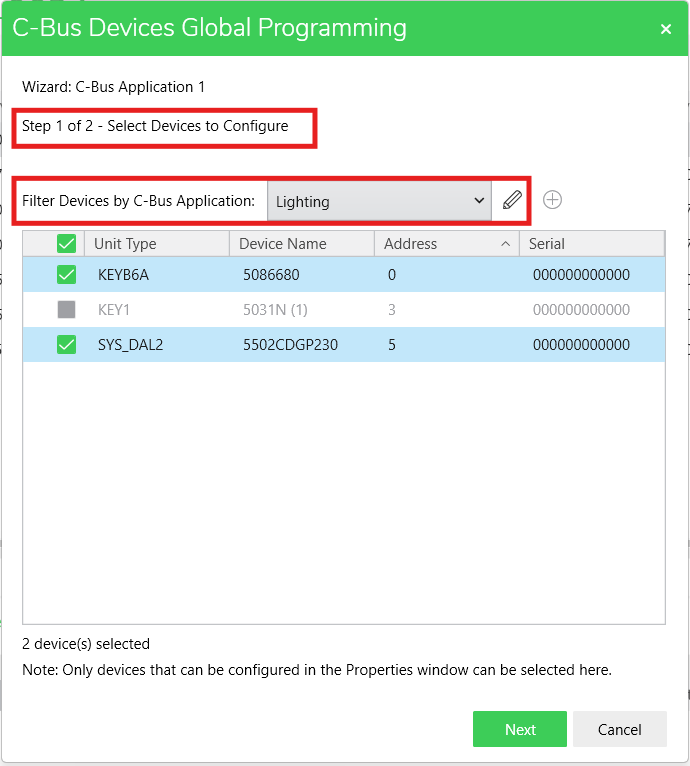
-
Select the application from the Filter Devices by C-Bus Application drop-down list. Devices are filtered based on the selected application.
-
Devices are not displayed in the device table if the selected new application is already configured for any other application property of the device.
-
Click
 to the edit the application name.
 -
The Edit Application pop-up appears.

-
Make necessary changes and click Save.
-
If you select C-Bus Application 1 – 4 wizard, in Step 2 of 2 — Select New Application to Set section, add application is displayed.

-
You can assign different application from the New C-Bus Application to Set drop-down list.
-
Click
 to add new application. Add Application pop-up appears.
-
Enter the name and click Create. The created application name is listed in the New C-Bus Application drop-down list.
-
The application selected in Application 1 drop-down list will not be listed in Application 2, Application 3 and Application 4 drop-down lists and vice versa.
-
-
-
If no devices are selected, Next button will be disabled.
-
Click Next.

Step 2 of 2 — Select the Time Threshold to Set section appears.

-
Select the required threshold from the Time Threshold drop-down list.
-
Click Run. The wizard starts to apply the changes.

-
If you try to close the C-Bus Devices Global Programming window during the process, an Error pop-up is displayed.

Once the changes are applied, success message appears.

-
-
Click Restart Wizard to navigate to Step 1 of 2 — Select PIR Devices to Configure section.
-
Click Close to close the C-Bus Devices Global Programming window.
-
If the PIR Unit Time Threshold wizard finishes with one or more device errors, the Partially completed message is displayed.

-
If the PIR Unit Time Threshold wizard finishes, where an error has occurred and changes were not applied/saved successfully to all devices from a list (including a single device only), then the Failed message is displayed.

-
Below are the scenarios when changes are applied and successfully completed, the configuration changes are displayed in the PROPERTIES window.
Wizard
Changes Applied
Changes reflected in PROPERTIES
C-Bus Application 1– 4


C-Bus Dimmer Min/Max Levels


Blocks and Widgets Timer Expiry Time/Duration


PIR and Multisensor Unit Time Threshold


PIR Enable/Disable Group Address and Mode


C-Bus Relay Turn On Level

