
Digital Dimmers
The SpaceLogic C-Bus Digital Dimmers are new-generation lighting control dimmers that helps to allow full customization for elegant control of dimmable LED lights and other light sources. The C-Bus dimmer is compatible with a range of load types.
-
Trailing edge for incandescent and capacitive input electronic transformer based LV lighting.
-
Leading edge for iron-core transformer based LV or neon lighting and other inductive loads.
Unit Types
-
DIMDD8 (5508D1D, 8 Channel 1A DIN Digital Dimmer with switchable C-Bus Power Supply)
-
DIMDD4 (5504D2D, 4 Channel 2A DIN Digital Dimmer with switchable C-Bus Power Supply)
-
DIMDH4 (5504DHD, 4 Channel High Power DIN Digital Dimmer with switchable C-Bus Power Supply)
To convert old dimmers to new dimmers, click here.
To upgrade Digital Dimmer firmware, click here.
To confirm channel dimming mode via live networks, click here.
To enable/disable Inbuilt C-Bus Power Supply function for the Digital Dimmers, click here.
 WARNING WARNING |
|---|
|
Dangerous voltages may be present on the output of dimmer
channels even though the dimming level is set to zero.
Avoid the risk of electrical shock that could result in
death or serious injury by disconnecting the unit from mains power
before accessing the output terminals or any connected wiring. This
condition is found on many dimming products.
Failure to follow these instructions can result in death, serious injury, or equipment
damage.
|
The field information to configure SpaceLogic C-Bus Dimmers is as explained below:
|
Name |
This field allows to modify the Dimmer device name. |
|
Type |
This field displays the default device type. |
|
Applications |
This section displays the lighting applications supported by the dimmers. Up to four lighting applications can be defined and then used throughout the configuration of the dimmers. |
|
NOTE: Name,
and Type are database properties only and not stored in device.
|
|
|
Channels NOTE :
|
Group This field allows to program group addresses associated with dimmer channels. You can:
|
||
|
Dimming Mode |
This field allows to select type of the Dimming Mode: Trailing Edge (TE) or Leading Edge (LE). |
||
|
Channel Name |
This field allows to define the channel name of the dimmer. |
||
|
Channel Location |
This field allows to define the channel location of the dimmer. |
||
|
Advanced |
Min Level |
This field allows to set the minimum level in percentage. |
|
|
Max Level |
This field allows to set the maximum level in percentage. |
||
|
Warn Before off Time |
This field allows to set the warn before off time. By default, it is Not enabled. |
||
|
Load Profile |
Load profile feature allows to set the dimming channel to operate on specific load. By default, the inbuilt load profile is connected to the dimming mode selected. Maximum
of 4 custom profiles can be selected using drop-down list. Custom
load profile can be modified using For more details on custom profile live testing, click here. |
||
|
Dimming Curve |
For more details, click here. |
||
|
Power Recovery |
This field allows to set the power recovery percentage. By default, it is Restore To Previous. |
||
|
Power On Delay |
This field allows to set the Power On Delay in hours: seconds format. |
||
|
Logic |
Type This field allows to select the type of the logic group. |
||
|
Logic Group This field allows to program logic group addresses associated with dimmer channels. You can:
|
|||

|
Warn Before off This section indicates warning off before the group address is turned off (1–15 minutes) based on the timings set. |
Warn Before off Enable Group It also allows to create a new group name which takes the next available address. In this section, you can :
By default, it is unused. If enable group is created, Restore To Previous is enabled. By typing new name in <unused> space allows you to create a new group name which takes the next available address. |
Restore To Previous If Restore To Previous is unchecked, recovery level is enabled to set. By default, Restore To Previous is checked. |
|
Recovery Level Recovery level percentage can be from 0 –100% |
|
Remote On/Off |
This field allows to choose the combinations of Remote On and Off for each individual channels. NOTE :
|
|
Error Reporting This section displays the fields for error reporting |
Firmware Version |
Applicable for firmware version below 1.1.0 |
Applicable for firmware version above 1.1.0 |
|
Device ID |
This field displays the unit address of the device. NOTE: The Device ID is for the entire device and
is as same for Measurement section.
|
This field displays the unit address of the device. NOTE: The
Device ID is for the entire device and is as same for Measurement.
When you assign a Device ID, and then if you set the Device ID to Not Assigned, then all properties in both the Error Reporting and Measurement section are reverted to their default settings and disabled (grey out state).  Mouse over on the Device ID info icon to view the tooltip message.  |
|
|
Mode Control Group |
This field allows to add an enable group (0–254). If you assign a group, Restore To Previous field is displayed and Regular Reporting Interval drop-down is enabled. If you uncheck Restore To Previous check box, Regular Reporting field will be enabled. If you check Restore To Previous check box, Regular Reporting will be disabled.  |
||
|
Regular Reporting |
This field configures the Error Reporting mode of the Dimmers into one of three modes:
|
This field configures the Error Reporting mode of the Dimmers into one of the modes:
All the modes can be set with the regular reporting interval set to No regular reports, which allows live reporting of errors without the regular reports. Mouse over on the Regular Reporting info icon to view the tooltip message. |
|
|
Restore to Previous If selected, this field restores the data on power failure. |
When you click Save with the below conditions:
The Regular Reporting displays the last saved value. Mouse over on the Restore to Previous info icon to view the tooltip message.  |
||
|
Regular Reporting Interval |
This field is used to select the time interval period between the completion of a regular report and beginning of the next report in Always On, Most recent only and Always On, Most recent and most severe modes. By default, the interval is 30 minutes. Regular reporting interval is enabled for Trigger only mode. |
||
|
Trigger Group |
This field contains a Trigger Group to trigger an error reporting event for any of the three error reporting modes. When a Trigger group is created, Resend Action Selector and Acknowledge Action selector are displayed. The Resend Action Selector is set to send all errors and Acknowledge Action selector is set to acknowledge all errors. |
||
|
Destination Network |
This field contains the destination C-Bus network to which the Dimmers routes the error reporting messages. This allows the error messages to be sent to a remote C-Bus network for central monitoring if it’s not the local network. Mouse over on the Destination Network info icon to view the tooltip message. |
||
|
Application Items |
The Property Editor displays the Application Items property only when you load a project C-Bus Dimmer device. When you load a live network C-Bus Dimmer device, the Property Editor hides this property because you can create application data only for a project device. Mouse over on the Application Items info icon to view the tooltip message. For more info on bulk creation of application data for dimmers, click here. |
||
|
Advanced |
C-Bus Voltage Warning Set Threshold |
|
|
|
C-Bus Voltage Warning Clear Threshold |
Mouse over on the C-Bus Voltage Warning Clear Threshold info icon to view the tooltip message. |
||
|
C-Bus Voltage Critical Set Threshold |
Mouse over on the C-Bus Voltage Critical Set Threshold info icon to view the tooltip message. |
||
|
C-Bus Voltage Critical Clear Threshold |
Mouse over on the C-Bus Voltage Critical Clear Threshold info icon to view the tooltip message. |
||
|
C-Bus Power Supply Warning Set Threshold |
Mouse over on the C-Bus Power Supply Warning Set Threshold info icon to view the tooltip message. |
||
|
C-Bus Power Supply Warning Clear Threshold |
Mouse over on the C-Bus Power Supply Warning Clear Threshold info icon to view the tooltip message. |
||
|
Unit Over Temperature Set Threshold |
This field is a combo box which is by default set to 70° C . The Unit Over Temperature Set Threshold property increments by 1° C with a range of 1° C - 80° C. Mouse over on the Unit Over Temperature Set Threshold info icon to view the tooltip message. |
||
|
Unit Over Temperature Clear Threshold |
This field is a combo box which is by default set to 65° C . The Unit Over Temperature Clear Threshold property increments by 1° C with a range of 0° C - 79° C. Mouse over on the Unit Over Temperature Clear Threshold info icon to view the tooltip message. |
||
|
Firmware Version |
Applicable for firmware version below 1.1.0 |
Applicable for firmware version above 1.1.0 |
||||
|
Measurement |
Device ID |
This field displays the unit address of the device NOTE: The Device ID is
for the entire device and is as same for Error Reporting section.
|
This field displays the unit address of the device. NOTE: The Device ID is
for the entire device and is as same for Error Reporting section.
When you assign a Device ID, and then if you set the Device ID to Not Assigned, then all properties in both the Error Reporting and Measurement section are reverted to their default settings and disabled (grey out state). Mouse over on the Device ID info icon to view the tooltip message. |
|||
|
Send Trigger Group |
This field contains a trigger group to request the Dimmers to send its stored measurement data. Mouse over on the Send Trigger Group info icon to view the tooltip message. |
|||||
|
Clear Trigger Group |
This field contains a trigger group to clear the stored measurement data in the dimmers. Mouse over on the Clear Trigger Group info icon to view the tooltip message. |
|||||
|
Regular Broadcast Interval |
NA |
Disabled by default. Can set the intervals between 1 min to 4 hours. |
||||
|
Regular Broadcast Option |
NA |
All |
Enabled by default |
|||
|
Lamp Hours |
Selected and Disabled by default |
|||||
|
Channel Temperature |
Selected and Disabled by default |
|||||
|
Power Supply Current |
Selected and Disabled by default |
|||||
|
C-Bus Voltage |
Selected and Disabled by default |
|||||
|
Unit temperature |
Selected and Disabled by default |
|||||
|
NOTE: Deselecting all will enable each
of the individual check box options.
|
||||||
| Destination Network |
This field contains the destination C-Bus network to which the dimmer routes measurement application messages. Mouse over on the Destination Network info icon to view the tooltip message. |
|||||
|
The action selector for trigger groups is as explained below: |
Virtual Channel Number |
Property |
Units |
Reset |
Notes |
|
|
0 – 15 |
Lamp Running Time |
Hours |
Yes |
NA |
||
|
16 – 31 |
Channel Voltage |
Volts |
No |
Units with power metering only |
||
|
32 – 47 |
Channel Current |
Amperes |
No |
|||
|
48 – 63 |
Channel Power |
Watts |
No |
|||
|
64 – 79 |
Channel Energy |
Watt-hours |
Yes |
|||
|
80 – 95 |
Channel Lifetime Energy |
Watt-hours |
No |
|||
|
128 – 143 |
Channel Temperature |
Celsius |
No |
Dimmers only |
||
|
252 |
C-Bus Power Supply Output Current |
Amperes |
No |
NA |
||
|
253 |
C-Bus Voltage |
Volts |
No |
NA |
||
|
254 |
Unit Temperature |
Celsius |
NA |
NA |
||
|
Measurement Application supports various operational parameters for triggered request. Measurement Request Trigger Group defines the Trigger Group for the request. A trigger's Action Selector determines which measured parameter is requested. NOTE: Action Selector 0xFF requests all measurements (in which they
are sent 2 at a time with an interval of 2 seconds). Other Action
Selector values can be used to request individual measured properties
corresponding to the virtual channel number as per the above table.
The DEVICE ID for the Measurements is defined by the Device ID parameter, the same Device ID is used for Error Reporting. The Device ID will be unique per network to differentiate measurements from different devices. The devices monitoring the Measurement messages should keep track of the source network to differentiate if Device IDs are reused across multiple C-Bus networks. If the Device ID parameter is left at its default value of 0xFF then the Unit Address is used as the Device ID in the Measurement Application messages, which ensures uniqueness. However, if the device is readdressed then any monitoring devices will also needs to be updated to match the new Device ID (It is recommended to leave the Device ID as the default value). |
||||||
|
Logic Groups Dimmers can have maximum 4 logic groups each group having respective channels (8 or 4) |
Group This section will
allow to create a enable group using By default, it is unused. If enable group is created, Restore To Previous is enabled. |
|
Power Recovery This field allows to set the power recovery percentage. By default, it is Restore to previous. |
|
|
Channel NOTE :
|
|
Global This section displays the project properties set by the user at the time of creation of the project. |
C-Bus Clock |
If checked, allows you to enable the C-Bus clock for the dimmers. |
|
Disable Local Toggle |
If checked, disables the local toggle. |
|
|
Network Hardware Burden |
If checked, the physical hardware burden is plugged into the device. By default, it is unchecked. |
|
|
Inbuilt C-Bus Power Supply |
If checked, the power supply is enabled/active. By default, it is unchecked. |
|
|
Disable Dimmer Mode Change |
If checked, disables the dimmer mode change. |
|
|
Disable Power Supply Toggle |
If checked, disables the power supply toggle. |
|
|
Disable C-Bus Priority |
If checked, disables the C-Bus priority. |
|
|
Disable Clock Generator Toggle |
If checked, disables the clock generator toggle. |
|
Unit Identification This section display the fields for identification of the unit. |
Unit Type |
This field contains the unit type and unit description of the device. |
|
Catalog Number |
This field contains the catalog number related to the unit type. |
|
|
Firmware Version |
This field shows the version number of the C-Bus interface firmware which exists on the physical network or which has been assigned to a logical representation of the unit in the database. |
|
|
Part Name |
This field contains the part name which is stored in the unit hardware, which can be modified. |
|
|
Unit Address |
This field displays the unit address assigned to the device. |
|
|
Serial Number |
This field contains the serial number which exists on the physical network. |
|
|
Tag Name |
This field contains the name that user can give to the logical representation of the unit. This name can be up to 32 characters long and is stored in the project database only. |
|
|
Notes |
This field contains a location to add notes about the unit which is stored in the project database only. |
|
Status The Status section contains information about the C-Bus network related functions located on the unit. |
Device Status This section displays the details of hardware. |
Hardware Version |
This field displays the hardware version of the device. |
|
Firmware Version |
This field displays the firmware version of the device. |
||
|
C-Bus Clock Active |
This field indicates whether the C-Bus internal clock is currently enabled on the Dimmers on the network. |
||
|
C-Bus Voltage (V) |
This field displays the C-Bus voltage of the device. |
||
|
Inbuilt C-Bus Power Supply Active |
This field displays whether the Inbuilt C-Bus Power Supply Active is On or Off. |
||
|
Power Supply Load |
This field displays the load of the power supply (mA). |
||
|
Power Supply Output Voltage |
This field displays the power supply output voltage (mV) of the device. |
||
|
Load Power |
This field displays the load power (mW) of the device. |
||
|
Unit Temperature |
This field displays the unit temperature (°C)of the device. |
||
|
Channel Status Each channel will have these channel status. NOTE :
|
Load Compatibility |
This field displays the status of load incompatibility (Yes/No). |
|
|
Dimming Mode |
This field displays type of the dimming mode. |
||
|
Offline |
This field displays the status of the device (Yes/No). |
||
|
Dimming Mode Error |
This field displays the status of dimming mode error (Yes/No). |
||
|
Temperature Wind Back |
This field displays the status of temperature wind back (Yes/No). |
||
|
Temperature Shut Down |
This field displays the status of temperature shut down (Yes/No). |
||
|
Over Current |
This field displays the status of over current (Yes/No). |
||
|
Operating Temperature |
This field displays the value of the temperature. |
||
|
Mains Frequency |
This field displays the value of the mains frequency. |
Once configuring dimmers is completed save the changes.
Load Profile
By adjusting settings within each dimmer channel, a Load Profile tailors dimming behavior for better end-to-end performance.
Inbuilt Load Profiles and the Inbuilt Dimming Curve have the pre configured settings which cannot be modified. If the acceptable results cannot be utilized with the load being used, the settings are customized and applied to a dimmer channel.
A Custom file can also be saved and used within other channels of the dimmer and also shared across other compatible dimmer devices.
Default Dimmer Channel Profile is selected to be the most universal. There are 4 user-configurable dimmer channel profiles. Each channel can be assigned to any one of these 5 profiles. In each case there is a improvement for the light source behavior during dimming, the load profile can be adjusted by the SpaceLogic C- Bus Commission Software.
The SpaceLogic C-Bus Commission software allows:
-
The customizing of the load profiles per channel.
-
4 user configurable profile per channel/device.
-
Saving and sharing of endless load profiles for future project uses.
-
Different load types:
-
LED Lighting (TE Dimmable)
-
LED Lighting (LE Dimmable)
-
Electronic Transformer (TE Dimmable)
-
Electronic Transformer (LE Dimmable)
-
Incandescent Lighting (TE Preferred)
-
Incandescent Lighting (LE)
-
Iron Core Transformer (LE)
-
Sweep Fan (LE)
-
Exhaust Fan (LE)
-
Other (LE)
-
Other (TE)
-
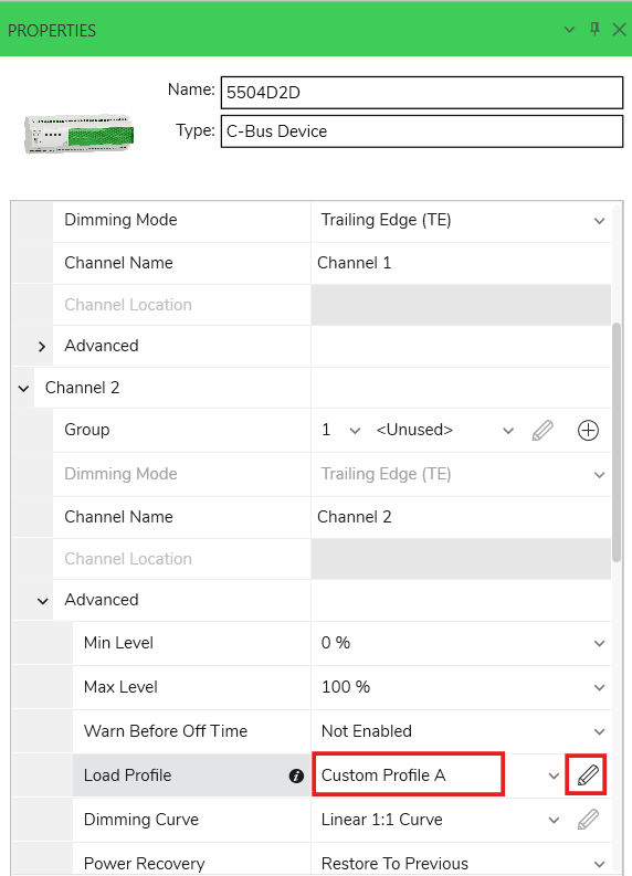
To create a customized load profile:
-
Under Advanced section of Channels, select any Custom Profile option from Load Profile drop-down.
-
Click
 .
.
Custom Load Profile and Dimming Curve window is displayed. The load profile customizing is done in Configuration tab.
For 50 Hz

For 60 Hz
 NOTE: The Custom Load Profile parameter values varies depending on the load type selected.
-
The lower limit for the Soft Turn On property is calculated dynamically. However the lower limit value is no less than 0.01.
-
The lower limit for the Soft Turn Off property is calculated dynamically. However the lower limit value is no less than 0.01.
-
The lower limit for the Kickstart Brightness is based on Minimum Brightness + 10.
-
The lower limit for the Kickstart Turn On property is calculated dynamically. However the lower limit value is no less than 0.01.
-
Selecting a Load Type will load specific values based on the selection of the Mains Frequency property.
IMPORTANT: When deploying a DIMDD8 / DIMDD4 dimmer, the dimming mode of each channel of the dimmer device loaded into the Property Editor are compared to the live dimmer device. If there is a conflict in the dimming mode of a channel :A Channel Dimming Mode Conflict window is displayed prior to deployment.

-
Click Yes to resolve the conflict and deploy.
-
Click No to cancel the deployment.
-
- SpaceLogic C-Bus Commission enables saving, uploading or sharing
of load profile files which includes the following :
-
Load Brand
-
Load Model
-
Load Quantity
-
Custom Notes associated with the load
-
Load Type
-
Read-only dimming mode
-
Mains Frequency
Dimming setting includes the following:

-
-
To edit the preset values, click on the value and type new value within the range which is mentioned next to the parameter.
-
Click
 to reset the parameter values.
Minimum Brightness: Sets the level where the load operates or is visibly On.
Maximum Brightness: Sets the level where the load exhibits no further change in brightness or output.
Soft Turn On: Sets the role of change for Instant Ramps. The value is the time taken to transit from Off to Maximum Brightness. This value can also affect the timing of C-Bus Ramps between levels and the output of a dimming curve, which is set to 1 second or less.
Soft Turn Off: Sets the role of change for Instant Ramps. The value is the time taken to transit from Off to ON.
Kickstart Duration: When enabled, sets the duration to maintain the Kickstart Brightness level before recovering to a lower level if set.
Kickstart Brightness: When enabled, sets the dimmer Kickstart Minimum Brightness level before when transition from Off to On (at any level).
Kickstart Turn On: When enabled, sets the time in which the Kickstart Brightness level is applied to the load. A value of 10 ms is a Fast or Hard Start (same as a switch). This value is recommended to be set to Fast between 0.010 ton 0.100 seconds.
Kickstart Recovery: When enabled, sets the time taken at the end of the Kickstart duration to transition from the Kickstart Brightness level to the currently set level of the load.
If the set level is less than the Kickstart Brightness level, this value is set to Slow to achieve a smooth unnoticeable transition at the end of the kickstart.
To reset both Load Profile and Dimming Curve set values, click Reset All.
Enter the required information in Load Brand, Load Model, Load Quantity and Profile notes and click OK.
The custom load profile settings created can be saved and used for other dimmer channels and dimmer devices by exporting the settings using Save To File. The Save to file is enabled once there is a change in the settings.
The exported custom load profile can be reloaded to use for other dimmers using Read From File . This will open the folder consisting of JSON files in the path
Select the file and click Open.

Custom Profile Live Testing
Custom Profile Live Testing allows you to quickly identify and define the minimum and maximum conduction values for a dimmer channel. It uses a direct connection to the dimmer and provides live control of the connected load, without repetitive deployment including:
-
Maximize dimming range of connected lights.
-
Mask erratic behavior of lights at low brightness levels.
-
Mask little/no change in response of lights at high C-Bus control levels.
-
Define attributes from live testing rather than experimenting or guessing values to try.
NOTE: The maximum conduction value has been changed to 9000 for High-powered dimmer (DIMDH4) and to 9500 for other dimmers.
To perform live testing on the dimmer:
-
In the PROPERTIES window, select any custom profile from the Load Profile drop-down and click
.
Custom Load Profile and Dimming Curve window is displayed.
-
You can perform live testing in the Testing section. The Testing tab is disabled initially and becomes enabled when the following conditions are met:
-
The C-Bus Network must be opened and scanned.
-
If the dimmer is invoked from project, dimmer must be partial or fully matched.
-
A group address must be set or configured to the channel.

The Testing tab displays the below properties of the dimmer:
-
Dimmer Device Name.
-
Dimmer Channel Name.
-
Current configured Load Profile for the channel.
-
Current configured Dimming Curve for the channel.
-
Current configured Dimming Mode for the channel.
-
Current configured Mains Frequency for the channel.
-
-
-
Click
 to start the testing.NOTE: The testing operation places the current dimmer channel into test mode, allowing you to explore, test and confirm its dimming capability with the connected load.
 -
Once the testing starts, the process takes place in three steps.
Step 1:

-
Set the lowest acceptable brightness level and click Set Value to set the value.
NOTE: Until you set the value and click Set Value, the Turn On and Turn Off buttons will be disabled. -
Click Turn On to test the turn on behavior at that level.
-
Click Turn Off to turn off the test at that level.
-
Click Step 2 to test the maximum brightness.
Step 2:

-
Set the highest acceptable brightness level.
-
Click Step 3 to test the dimming response.
Step 3:

-
Choose the ramp rate response between the Minimum and Maximum Brightness limits with the load currently connected, to test and observe the dimming behavior within the range defined in Step 1 and Step 2.
The ramp rate ranges are instant, 4 secs, 8 secs, 12 secs, 20 secs, 30 secs.
-
Click Save.
NOTE: If a validation error occurs, the step arrows and labels are disabled.
-
Dimming Curve
A Dimming Curve refers to a translation between input level and output level. A Dimming Curve adjusts the rate of the change of the brightness level of a dimmer channel as the C-Bus group (level) is ramped. The default dimming curve is linear.
To create a customized Dimming Curve:
-
In Advanced section of channels, select Custom Curve from the Dimming Curve drop-down.
-
Click
.
Custom Load Profile And Dimming Curve window is displayed.
-
To add new point on chart, right click on the chart and select Add.
-
To change the added point, hold and drag the point to set new channel and control range value.
Once settings are completed mention curve notes and confirm OK.
The chart in below image represents mapping between load profile and C-Bus control range.

The custom dimming curve settings created can be saved and used for other dimmer channels and dimmer devices by exporting the settings using Save To File. The Save to file is enabled once there is a change in the settings.
-
Click
to reset the setting values.The exported custom dimming curve can be reloaded to use for other dimmers using Read From File . This will open the folder consisting of json files in the path .
-
Select the file and click open.
