
Advanced Configuration SENPIRIB
-
Click Advanced Configuration in the Configuration section of PROPERTIES.
The Advanced Configuration SENPIRIB dialogue box appears. The below configurations can be performed in the Advanced Configuration :
Mode
-
In the Mode section, select the required option from the Mode drop-down list. Refer the below table for option description.
Presence Detection with Light Level Target
It sets the sensor for presence detection regardless of light level conditions. When the sensor element detects motion the multi sensor sends a C-Bus ON command to the group and resets the time out period.
Presence Detection
When Presence Detection is selected, the sensor triggers on motion. When the sensor detects motion, it sends a C-Bus command on the C-Bus network.
Sunset Switch
It turns the lighting type group ON when the measured lux level is low. Low lux levels typically occur during sunset and sunrise. When the lux level falls below the configured threshold setpoint, the function activates.

-
Refer the below table for configuration in the Light Level Target (Lux) section.
Target (Fixed Lux)
You can update the Light Level Target by adjusting either Target (Fixed Lux) or the Light Level Slider.
-
Changing the Light Level Slider updates Target (Fixed Lux), and changing Target (Fixed Lux) updates the slider.
-
You can increase or decrease Target (Fixed Lux) in increments of 1.
-
You can set Target (Fixed Lux) within the range 0 to 2000.
-
Target Range is displayed next to Target (Fixed Lux) based on the selected Margin (Fixed %).
-
You can calculate Target Range using Target (Fixed Lux) and Margin (Fixed %).
Margin (Fixed %)
You can update the Light Level Margin by adjusting either Margin (Fixed %) or the Light Level Slider.
-
Changing the Light Level Slider automatically updates Margin (Fixed %), and changing Margin (Fixed %) automatically updates the slider.
-
By default, Margin (Fixed %) is set to 6%, which corresponds to 42 Lux.
-
You can increase or decrease Margin (Fixed %) in increments of 1.
-
You can set Margin (Fixed %) to any value from 1 to 100.
-
The corresponding Lux value is displayed in the format (XX Lux), when you change the Margin (Fixed %).
Current State
-
Current State indicates the operating state of the sensor—Light, Dark, or In Target Range—based on the current light-level reading relative to the Light Level Target and Light Level Margin.
-
You can set Current State to Dark when the current light level is lower than the lowest value in the Target Range.
-
You can set Current State to In Target Range when the current light level is between the lowest and highest values in the Target Range
-
You can set Current State to Light when the current light level is higher than the highest value in the Target Range
-
-
The current light level is displayed in Lux when the network is open and the project device is matched to a live network device.
-
Click
 to update the Current State value.
 -
Example : Current State values — Dark (150 Lux) and Light (1000 Lux).

-
-
Refer the below table for configuration in the Potentiometer A section.
Function
The Function drop-down list has below options:
-
Unused
-
Light Level & Sunset Adjust
-
Block Timer Adjust
-
Occupancy Sensitivity Adjust
By default, Function is set to Light Level & Sunset Adjust.
Block
Block field is disabled when Function is set to Unused, Light Level & Sunset Adjust, or Occupancy Sensitivity Adjust.
Block field is enabled when Function is set to Block Timer Adjust.
Level
The current Level is displayed when the network is open and the project device is matched to a live network device. For example Level values for each Function include:
-
Unused: Level = 122
-
Light Level & Sunset Adjust: Level = 290 to 370 Lux
-
Block Timer Adjust: Level = 0 H 2 M 22 S
-
Occupancy Sensitivity Adjust: Level = 47%
Click Refresh to update the Level value.

-
-
Refer the below table for configuration in the Group section.
Group
-
Select the value from the Application Index drop-down list.
-
The Group field displays all available groups within the selected application.
-
You can add and edit Groups. For more information refer Group.
Select the desired expiry time.
NOTE: The Expiry Time field ranges from 0 to 18 hours, 12 minutes, and 15 seconds.-
You can increase or decrease the hours and minutes by increment of 1.
-
You can increase or decrease the seconds by increment of 5.
-
You can also input a value manually to hours, minutes, and seconds.
 NOTE: When you select No mode Set (Advanced Configuration) from Mode drop-down list in Mode section, Group drop-down list and Expiry Time field are disabled.
 -
-
Refer the below table for configuration in the Light Level Maintenance Activation section.
Active
Only when you select the Active check box, the Group field is enabled.
When you assign a Group, the Enable and Disable radio buttons are enabled.

Mouse over on the Application Index to view the tool tip message.

Group
-
Select the value from the Application Index drop-down list.
-
The Group field displays all available groups within the selected application.
-
You can add and edit Groups. For more information refer Group.
-
Select Enable to activate the sensor and Disable to deactivate the sensor.

-
-
Refer the below table for configuration in the Occupancy Enable/Disable section.
Group
-
By default, Application Index is set to 1 and disabled for your selection.
-
The Group field displays all available groups within the selected application.
-
You can add and edit Groups. For more information refer Group.
-
Mouse over on the Application Index to view the tool tip message.

-
Virtual Keys
The SENPIRIB provides eight virtual keys that you can program in the same manner as wall switch input keys. You can assign each virtual key to an application. You can associate a macro function with each virtual key. By default, the first three virtual keys assigned are the Day Move, Night Move, and Sunset macro functions.
-
Click Virtual Keys 1–4 tab.
The Virtual Keys 1, Virtual Keys 2, Virtual Keys 3, Virtual Keys 4, Occupancy Enable/Disable, Join Mode and Assign Occupancy (PIR) Events to Virtual Keys section appears.

-
Based on the Mode selected on the Configuration section (or) Mode tab
:-
Virtual Keys 1–8 are set to the corresponding Function(s) and Group(s), and vice versa.
-
Light Level Target/Margin is set to Fixed.
NOTE: For a live network device or a project with an existing configuration, the Mode is set according to the current device configuration. -
All Virtual Key properties such as Application Index, Group, Function(s), and any other related properties are updated based on the selected Mode.
-
Refer to the table below for details on Virtual Key masking based on the selected Mode.

-
-
Refer the below table for configurations in the Virtual Key 1 section.
Function
Select the required option from the drop-down list.
When you select On, Off On Up, Off Down, Dimmer Up, Dimmer Down, Soft Up, Soft Down, Day Move, Night Move, Shutter Toggle, Shutter Open Toggle, Shutter Close Toggle, Shutter Open, Shutter Close, Bellpress and Shutter Stop, the Expiry Time and Expiry Function fields are automatically hidden, as these options do not use expiry settings.

-
If you select On, On Up, Dimmer Up, Soft Up, Day Move, a confirmation pop-up appears and prompts you to apply the complementary function to the paired key. (Example: If one key is On, the other should be Off)

-
Click Yes to proceed and No to cancel the operation.
-
-
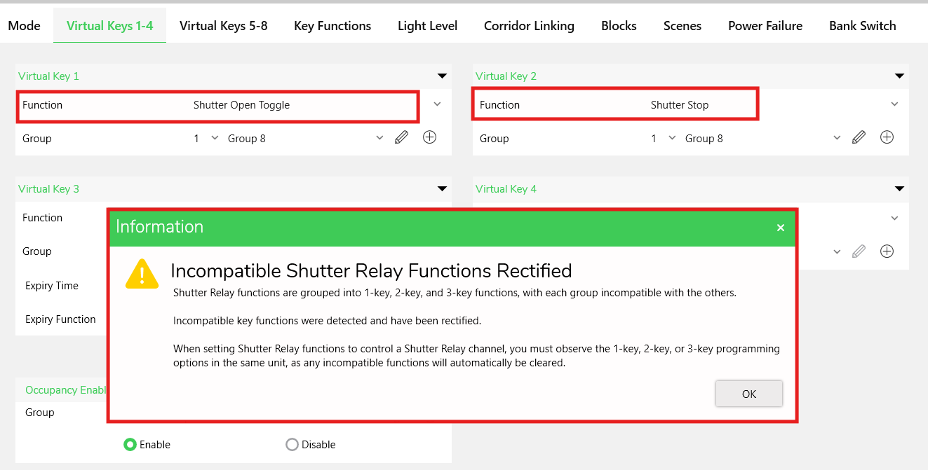
If you select any other shutter function combination, a warning pop-up appears.
-
If you select Preset 1, the below fields appear.

-
In the Level field, either drag the slider to set the value or select a level from the drop-down list.
-
-
If you select Timer, the below fields will appear.

-
Select the Timer Type.
-
-
If you select Scene or Fan Speed Cycle, the below fields will appear.

-
Select Scene 1 from Scene drop-down list when no Scenes are assigned in the device.
-
Select Scene 3 when Scene 1 and Scene 2 are already assigned to other keys.
-
You can edit and add a new trigger group to the application.
NOTE: The Trigger Group address field lists the available trigger groups in the selected Application. - To add/edit the Trigger Group refer Group.
-
You can edit and add a new action selector to the application.
NOTE: The Action Selector field lists the available action selector in the selected Application. -
Select the value from the Ramp Rate drop-down list.
-
Click
 next to the Scene drop-down list. The Scene Manager window appears. For more information, refer Scene
Manger.
next to the Scene drop-down list. The Scene Manager window appears. For more information, refer Scene
Manger.
-
Group
To add Group:
-
You can enter the name in Group field and press Enter in keyboard. The Group Name is created by taking the next available Group Address.
The created Group is saved in the network.
or,
-
Click
 . The Add Group pop-up
appears.
. The Add Group pop-up
appears.
-
Enter the required details and then click OK. The Group Name is created and listed in the Group drop-down list.
NOTE:-
Use a unique application name for each network.
-
Enter a maximum of 32 characters for the Group Name
-
You can use numbers, letters and special characters excluding /,” and #.
-
-
Click Cancel to cancel the operation.
To edit Group Name:
-
Click
 to modify the group name.NOTE: Edit button is disabled if the Group is set to <Unused>.
-
Make necessary changes and then click OK. You cannot edit the Group Address after it has been created.
-
When you select groups for an Application (1, 2) and update the Application Index, the inline confirmation pop-up is displayed for each selected group.

-
Click OK to create the missing groups.
-
Expiry Time
Select the desired expiry time. Mouse over on the Expiry Time info icon to view the tooltip message.
-
When you set the expiry time to 00 H: 00 M: 00 S, and configure the Virtual Key function as an occupancy function (Day Move, Night Move, Sunset, Any Move) or a Timer function, time validation error is indicated by a red border. Mouse over on the Expiry Time field to view the tool tip message.

-
If you click OK while an expiry time validation error exists for an occupancy function (Day Move, Night Move, Sunset, Any Move) or a Timer function, an Error pop-up is displayed.

 NOTE: The Expiry Time field ranges from 0 to 18 hours, 12 minutes, and 15 seconds.
 -
When you select an occupancy function (Day Move, Night Move, Sunset, Any Move) or a Timer function, for a Virtual Key:
-
Expiry Time is set to 00 H: 05 M: 00 S, and corresponding Block Timer 1 value is updated only if the timer was previously set to 00 H: 00 M: 00 S. Otherwise, the existing value is retained.
-
You can set the Expiry Time from 1 second to 18 hours, 12 minutes, and 15 seconds for occupancy and timer functions. For non-occupancy functions, you can set the Expiry Time from 0 seconds to 18 hours, 12 minutes, and 15 seconds.
-
Expiry Function
Select the expiry function from the drop-down list.
If you select Recall 1 / Recall 2, the below fields are displayed.

-
You can set a preset Level or select an existing Tag. The Level value ranges from 0–100% and 0–255.
NOTE: The default Level is 100%, 255 for Preset 1 and 0%, 0 for Preset 2.-
The percentage value increments by 1% (0–100%).
-
The level value increments by 1 (0–255).
-
You can update the Level by changing either the percentage or the level value.
NOTE:When you change the percentage, the level updates. When you change the level, the percentage updates.
-
-
The Tag field lists the available Levels for the selected Group Address.
-
When you select a Tag, the Level field updates to the Tag’s Level.
-
When you select a Level that matches a saved Tag, the Tag field updates to the corresponding Tag.
-
You can edit an existing Tag or add a new Tag to the Group Address.
-
The Add Tag option is enabled only when a Group Address is assigned to the Virtual Key.
-
- To add Tag:
-
You can enter the name in Level Name field and press Enter in keyboard. The Level Name is created by taking the next available Level Address.
The created Level is saved in the network.
or,
-
Click
. The Add Level pop-up
appears.
-
Enter the required details and then click OK. The Level Name is created and listed in the Tag drop-down list.
NOTE:-
Use a unique application name for each network.
-
Enter a maximum of 32 characters for the Level Name
-
You can use numbers, letters and special characters excluding /,” and #.
-
-
Click Cancel to cancel the operation.
To edit Level Name:
-
Click
to modify the Level Name.NOTE: Edit button is disabled if the Tag is set to <Unused>.
-
Make necessary changes and then click OK. You cannot edit the Level Address after it has been created.
-
-
-
Repeat the step 2 and step 3 for the configurations in Virtual Keys 2, Virtual Keys 3 and Virtual Keys 4 sections.
-
In Occupancy Enable/Disable section, select group from the drop-down list. You can add/edit the group. For more information on adding and editing group, refer Group.

Select Enable to activate the sensor and Disable to deactivate the sensor.
-
In Join Mode section, select the required application from the Join Application drop-down list. You can edit the application.
-
Select the required group from the Join Group drop-down list. You can add/edit the group.
NOTE:-
Group addresses assigned to Virtual Key Groups (1 to 8) are excluded from the Join Group drop-down list and vice versa.
-
Group addresses assigned in Join Group are excluded from the Link Group drop-down list in Corridor Linking.
-
Join mode extends the functionality of wired key input units by allowing the use of different macro functions for key inputs. This feature is particularly useful for remotely controlling lighting in spaces such as auditoriums or conference halls that can be partitioned.
-
When two spaces are joined (not partitioned), the key input units share common lighting control. When the spaces are partitioned, Join mode can be disabled, allowing the lighting in each partitioned area to be controlled independently.
-
Once group is assigned, a Confirmation pop-up is displayed.

-
Click Yes to continue. The Information pop-up is displayed.

Click OK or Exit icon to close the Information pop-up.
-
Click No to cancel the operation in Confirmation pop-up.
-
-
Once a group is assigned and Join Mode is in use:
-
Join Application and Join Group properties in both the Virtual Keys 1–4 tab and the Virtual Keys 5–8 tab are highlighted in light green.

-
J5 to J8 columns in the Keys Using Block section of the Blocks tab are highlighted in light green.

-
Virtual Keys 5–8 tab remains selected and in view (unlike Toolkit, which redirects you to the Blocks tab).
-
-
-
When you assign a Group Address for Virtual Keys 1 to 8, the corresponding Group field in Assign Occupancy (PIR) Events to Virtual Keys section is updated with the same Group Address.
Selecting an Occupancy Function to Virtual Keys automatically selects the corresponding Occupancy Event under Assign Occupancy (PIR) Events.
-
Assign Day Move to check Motion in Light (Day)
-
Assign Night Move to check Motion in Dark (Night)
-
Assign Any Move to check Any Motion
-
Assign Sunset to check Light Level (Sunset)
-
-
If you select No Mode Set (Advanced Configuration) in Mode drop-down list, the default occupancy event configuration for Virtual Keys 1 to 8 are as follows:
Keys
Option selected
Key 1
Motion in Light (Day)
Key 2
Motion in Dark (Night)
Key 3
Light Level (Sunset)
Key 4
No occupancy
Key 5
No occupancy
Key 6
No occupancy
Key 7
No occupancy
Key 8
No occupancy
-
When you select an Occupancy Function or Micro Function combination for a Virtual Key Group, the following Occupancy Event is selected:
-
Day Move function — only Motion in Light (Day)
-
Night Move function — only Motion in Dark (Night)
-
Any Move function — only Any Motion
-
Sunset function — only Light Level (Sunset)
-
-
You can select the following Occupancy Event combinations:
-
Only Motion in Light (Day)
-
Only Motion in Dark (Night)
-
Only Any Motion
-
Only Light Level (Sunset)
-
Motion in Light (Day) + Light Level (Sunset)
-
Motion in Dark (Night) + Light Level (Sunset)
-
Any Motion + Light Level (Sunset)
-
-
When you update the Assign Occupancy (PIR) Events to Virtual Key setting, the corresponding Virtual Key Group – Function is not updated.
-
When you change the Virtual Key Group – Function from an Occupancy Function to a Non-Occupancy Function, the previously selected Occupancy Event is retained for the key.
-
-
When a Block is selected for Light Level Broadcast, that Block is disabled for the Assign Occupancy (PIR) Events to Key selection.
-
Once configuration is done, click OK to save the configurations.

-
If you click Cancel or Exit icon without saving the configuration, a confirmation pop-up appears.

-
Click Yes to save the configuration and click No to cancel the confirmation pop-up.
-
Click Virtual Keys 5–8 tab.
The Virtual Keys 5, Virtual Keys 6, Virtual Keys 7, Virtual Keys 8 and Occupancy Enable/Disable section appears.
Repeat the steps 2–7 for the configurations in Virtual Keys 5, Virtual Keys 6, Virtual Keys 7, Virtual Keys 8 and Occupancy Enable/Disable sections.
Key Functions
The Key Functions tab provides advanced configuration options for key input units and sensors. For traditional C-Bus key input units, key functions are assigned to 4 press and release events. Refer the below table for the micro function and its action.
|
Micro Function |
Action |
|
Short Press |
when you first press the input key after the debounce time. |
|
Short release |
when you release the input key before the long-press time is reached. |
|
Long press |
when you press and hold the input key longer than the long-press time. |
|
Long release |
when you release the input key after a long press. |
-
Click Key Functions tab.
Key Functions section appears.

-
You can update the Micro Function combination.
-
Refer the below table for default Micro Function mapping.
Function
Short Press
Short Release
Long Press
Long Release
Night Move
On Key
Retrigger Timer
Retrigger Timer
Idle
Day Move
Retrigger Timer
Idle
Idle
Idle
Any Move
Retrigger Timer
Retrigger Timer
Idle
Retrigger Timer
Sunset
On Key
Off Key
Retrigger
Off Key
Unused
Idle
Idle
Idle
Idle
On
On Key
Idle
Idle
Idle
Off
Off Key
Idle
Idle
Idle
On/Off
Toggle
Idle
Idle
Idle
Dimmer
On Key
Up Mem Toggle2
Downcycle
End Ramp
On Up
Idle
Up Key
Up Key
End Ramp
Off Down
Idle
Mem Toggle2
Down Key
End Ramp
Timer
Toggle
Retrigger Timer
Idle
Retrigger Timer
Bell Press
On Key
Off Key
Off Key
Off Key
Dimmer Up
Idle
On Key
Up Key
End Ramp
Dimmer Down
Idle
Off Key
Down Key
End Ramp Soft Up
Idle
Ramp Off
Down Key
End Ramp
Soft Down
Idle
Ramp Off
Down Key
End Ramp
Preset 1
Recall 1
Recall 1
Ramp Off
Idle
Preset 2
Recall 1
Recall 1
Ramp Off
Idle
Shutter Toggle
Recall 1
Idle
Idle
Idle
Shutter Open Toggle
Recall 1
Idle
Idle
Idle
Shutter Close Toggle
Recall 2
Idle
Idle
Idle
Shutter Open
Recall 1
Idle
Idle
Idle
Shutter Close
Ramp Off
Idle
Idle
Idle
Shutter Stop
Recall 2
Idle
Idle
Idle
Fan Speed Cycle
Scene
Scene
Scene
Scene
Scene
Scene
Scene
Scene
Scene
Custom
Idle
Idle
Idle
Idle
NOTE: The Fan Speed Cycle and Scene micro-function combinations are read-only and non-editable. -
If you update the Micro Function combination, the respective Virtual Key group function is updated accordingly on Advanced Configuration 1-4 (or) Advanced Configuration 5-8 tabs vice versa (except for Custom).
The Custom function is excluded from this automatic synchronization.
-
If you select any micro-function combination other than the default values listed in the table, the Virtual Key group function is automatically set to Custom.
-
If you select Scene or Fan Speed Cycle function:
-
The micro-function combination is set to Scene.
-
The Function displayed on the Virtual Keys is determined by the micro-function combination.
-
Since Fan Speed Cycle uses the same micro-function mapping as Scene, the Virtual Key function is displayed as Scene.
-
Light Level
The Light Level contains parameters for controlling light level messaging.
|
Configuration in PROPERTIES |
Mode |
 |
 |
-
Click Light Level tab. Refer the below table for field description.
Field
Description
Target
The Target section contains parameters for setting the light level target and margin value. The target represents the lux level set point and the margin determines the percentage hysteresis. The Detector allows you to choose either a fixed lux set point or a Lighting group.
Fixed Lux
There are two values which determine the fixed level at which the Detector responds to a change in ambient lighting levels: the target lux and the margin %. The target value is the lux level set point and the margin % defines a hysteresis around the set point. It is possible to have a fixed lux level and a variable margin by selecting a Lighting group.
Group Values
When the Lighting group has been selected, the lux level set point or the % margin are defined as a Lighting group value.
Margin
The Margin % slider sets the hysteresis around the target lux level set point. This can be used to prevent the constant switching of relay levels or constant changes of dimmer levels when the ambient light level varies regularly (perhaps due to passing clouds). It means that a Lighting group, for example, can be set to turn on at a level below the target lux level set point, and turn off at a level above the target lux.
The Margin radio buttons allows you to choose a fixed percentage or a variable percentage based on a Lighting group value. When clicking the Fixed radio button, the percentage slider bar appears. When clicking the Group radio button, the Group drop down list appears.
Target Range — Displays the target range based on the inbuilt formula.
-
In Target section:
-
You can adjust the Fixed Lux value using either a slider or a drop-down list, in increments of ten.

-
If you enter a Lux value that is not a multiple of ten, it automatically resets to the nearest multiple of ten.
-
By default, the Fixed (Lux) is set to 700. You can set the Light Level Target from 0 to 2000 Lux.
-
-
Select the Group radio button:

-
The Application Index is set to Application 1 and is disabled for selection.
-
Mouse over on the Application Index, to view the tooltip message.

-
The Group Address drop-down list lists the groups available in the selected application.
-
-
-
In Margin section:
-
By default, the Margin Fixed (%) is set to 6, which is 42 Lux.
-
If you update Light Level Margin on the Configuration section (or) Mode tab, the set values are reflected and vice versa.
-
You can adjust the Fixed Lux value using either a slider or a drop-down list. You can set Light Level Margin from 1 to 100 Lux.
-
Select the Group radio button:
 NOTE: The Margin Fixed (%), and Margin Group radio buttons are enabled only if the Target Fixed (Lux) is selected.
-
The Application Index is set to Application 1 and is disabled for selection.
-
Mouse over on the Application Index, to view the tooltip message.
-
The acceptance criteria from 15 to 40 apply to the Margin Group.
-
To add and edit a group, refer Group.
-
-
-
When you select a group address for the Light Level Target Group/Light Level Margin Group, a level slider is displayed.
Light Level Target Group
Light Level Margin Group


-
Adjust the slider to set the corresponding group address to the selected level.
-
The level selected is displayed inline to the group address.
NOTE: Level slider is displayed only when SENPIRIB device is partially or fully matched in Project Devices and Network Devices sections.
-
-
The Target Range is set to Variable when Group radio button is selected.

-
In Ambient Light section:
Refer the below table for field description.
Field
Description
Ambient Light
Contains the Last Measurement field for showing the most recent ambient light level.
Last Measurement
Displays the current operating state of the sensor-Light or Dark—based on the current light-level reading relative to the configured light-level target. It also includes the current light-level value in Lux when the network is open and the project device is matched to a live network device.
Refresh
When the Refresh check box is selected, the ambient light level will be refreshed in five second intervals.
-
In Light level Maintenance section:
Refer the below table for field description.
Field
Description
Light level Maintenance
The Light Level Maintenance section provides the functionality for continuously controlling the light level of a Lighting Type group so that the measured light level lies within a desired range. The light range is determined by the range established in the Light Level Target section. Light level maintenance will use this range to set the maintenance light level range.
Active Check box
The Active check box activates light level maintenance functionality.
Block
The Block drop down list sets the selected Lighting Type group which will have light level maintenance assigned to it.
Group
The Enable Group drop down list assigns an Lighting Type group which will enable or disable maintenance functionality. Assigning a Lighting Type group to another key will make it possible to enable/disable light maintenance. Requires a pre-defined Lighting Type group, but not one which has been assigned a block function.
-
Select the Active check box. Only when you select it, the Block and Group fields are enabled. The Active check box activates light level maintenance functionality.
-
Select the required option (block or group address) from the Block drop-down list.
NOTE:-
Group addresses assigned to the Blocks are not available for selection.
-
Group address selected are assigned to the next available Block.
-
If all 8 Blocks have been assigned, group addresses, application addresses are not available for Block selection.

-
-
In Group drop-down list, select the required group address. To add and edit a group, refer Group.
-
Select Enable radio button to enable the light level maintenance when the Lighting Type group is on.
-
Select the Disable radio button to disable the light level maintenance when the Lighting Type group is on.
-
-
In Light Level Broadcasting section:
Refer the below table for field description.
Field
Description
Light Level Broadcasting
This feature keeps other units synchronised with the light level measured by the Occupancy/Light Level Detector, ensuring uniform illumination across large areas. The detector converts the measured light level from the photo-electric cell (PE cell) into a value between the minimum and maximum limits for the selected Lighting Type group (fully off to fully on) and broadcasts this value to the configured group.
Active Check box
The Active check box activates light level broadcasting function.
Block
The Block drop down list selects the block function where the broadcasting interval will be set. The block function must be assigned a Lighting Type group to which light levels will be broadcast. Block assignment for light level broadcasting has a fixed configuration. The block micro function field Expiry is automatically set to the Start command. The recommended minimum timer interval is ten seconds to minimise C-Bus traffic congestion. Once the Block drop down list has been activated using the Active check box, it is not possible to select a block function associated with a Lighting Type group assigned to one of the following macro functions:
-
Day Move
-
Night Move
-
Sunset
-
<SCENE>
-
Select the Active check box. Only when you select it, the Block and Expiry Time drop-down lists are enabled.
- Select the required option (block or group address) from the Block drop-down list.
NOTE:
-
Blocks configured with Occupancy Events (Day Move, Night Move, Any Move, Sunset), Scene, or Fan Speed are excluded from the selection list.
-
Block set for Light Level Maintenance is not listed for selection and vice-versa.
-
-
Select the desired expiry time. For more information, refer Expiry Time.

-
Corridor Linking
Corridor linking with sensors is an effective solution for office environments. It allows employees to arrive and leave without manually switching multiple lights on or off.
Example: When employees arrive at the office in the morning, they walk through the corridor and trigger an occupancy sensor, which turns on the corridor lights. As they enter their office, the multi-sensor detects occupancy and switches on the office lights. Once the office lights are on, the corridor linking function keeps the corridor lights on.
When the last employee leave the building, they turn off the office lights. This action triggers a lighting sequence that keeps the corridor lights on, allowing them to walk safely down the corridor and exit the building. After a configured delay, the corridor lights automatically turn off.
-
In Corridor Linking section, select the Enable Corridor Linking check box.
 NOTE: Only if you select the Enable Corridor Linking check box, other all drop-down lists will be enabled.
 -
In Link Group drop-down list, select the required group address.
-
Mouse over on the Application drop-down list to view the tool tip message.
-
The Link Group drop-down list displays all available groups within the selected application.
-
You can add and edit Groups. For more information, refer Group.
NOTE:-
The selection of a Group Address is optional when selecting a Corridor Block or Office Block.
-
Group addresses assigned in Corridor Block and Office Block are reflected in group address in Block Assignments in Blocks tab and vice-versa.
-
-
In Corridor Block drop-down list, select the corridor block. Mouse over on the Corridor Block info icon to view the tooltip message.
-
In Expiry Time drop-down list, select the desired expiry time.
NOTE: The Expiry Time field ranges from 0 to 18 hours, 12 minutes, and 15 seconds.-
You can increase or decrease the hours and minutes by increment of 1.
-
You can increase or decrease the seconds by increment of 5.
-
You can also input a value manually to hours, minutes, and seconds.
-
Mouse over on the Expiry Time info icon to view the tooltip message.
-
Expiry Time set in Corridor Block and Office Block are reflected in Expiry Time in Timer section in Blocks tab and vice-versa.
-
When you set the Expiry Time to 00 H: 00 M: 00 S, time validation error is indicated by a red border. Mouse over on the Expiry Time field to view the tool tip message.

- If you click OK while an expiry time validation error exists
for a Timer function, an Error pop-up is displayed.

-
-
In Expiry Function drop-down list, select the required option.
NOTE:Expiry Function set in Corridor Block and Office Block are reflected in Expiry in Timer in Blocks tab and vice-versa.
-
In Office Block drop-down list, select the required option. You can select same (or) different blocks for Corridor Block and Office Block.
-
Mouse over on the Office Block info icon to view the tooltip message.
-
For more information on Expiry Time and Expiry Function, refer step 4 and 5.
-
Blocks
The Blocks table displays the operating configuration for the key-input portion of the unit. Each row lets you associate a Lighting compatible group with one or more input keys. In this tab, you define recall levels, timer values, and expiry key functions. You also assign LED indicators in the Blocks tab.

-
In Block Assignments section:
-
Select the application index from the Application Index drop-down list. By default, the application index for Blocks 1–8 is set to Application 1.
-
Select the group address from the Group drop-down list based on the selected Application. By default, the group for Blocks 1–8 is set to <Unused>.
-
Once you update the Application Index or Group Address, the Virtual Keys 1–8 group addresses are updated, and vice versa.
NOTE:Block Assignments, Keys Using the Block, and LED Assignment are disabled when a Scene or Fan Speed Cycle function is assigned to a Virtual Key.

-
-
In Recall Lvls section:
-
Select the recall value from Recall 1 drop-down list. By default, the Recall 1 value for Blocks 1–8 is set to 100.
-
Select the recall value from Recall 2 drop-down list. By default, the Recall 2 value for Blocks 1–8 is set to 0.
-
Any changes made to Recall 1 and Recall 2 are saved to the corresponding Block and reflected under the associated Key(s).
-
Changes to Recall 1 and Recall 2 remain synchronized across Functions (Preset 1 and Preset 2), Blocks, and Keys, and vice versa.
-
-
In Timer section:
-
You can increase or decrease the hours and minutes in increments of 1 in Timer 1 field.
-
You can increase or decrease the seconds in increments of 5 in Timer 1 field.
-
You can manually enter values for hours, minutes, and seconds. By default, the Timer 1 value for Blocks 1–8 is set to 00 h : 05 m : 00 s.
-
Select the required option from the Expiry drop-down list. By default, the Expiry value for Blocks 1–8 is set to Off Key.
-
Changes to the Timer or Expiry drop-down list are saved to the corresponding Block and reflected under the associated Key(s).
-
Changes to the Timer and Expiry settings remain synchronized with the Timer function, and vice versa.
-
When the Timer 1 value of Blocks is less than 1 minute and you select that block as a Corridor Block and/or Office Block:
-
The Expiry Time under Corridor Block and Office Block in the Corridor Linking tab is set to 00 h : 05 m : 00 s.
-
The corresponding Block Timer 1 value is also set to 00 h : 05 m : 00 s.
-
-
Example: If you assign Block 3 as a Corridor Block and Block 4 as an Office Block:
-
The Expiry Time for both Corridor Block and Office Block is set to 00 h : 05 m : 00 s.
-
The Timer 1 values for Block 3 and Block 4 are set to 00 h : 05 m : 00 s.
-
-
When you set the Timer 1 value in the Blocks tab to less than 1 minute and configure the block as either a Corridor Block or an Office Block, the Timer 1 value automatically resets to 00 h : 01 m : 00 s.
-
-
In Keys Using the Block section:
-
The following keys will be selected by default with Block and Key combination.

-
If you do not assign a Block to a Virtual Key, the Virtual Key Group Address on the Keys tab is set to Unassigned.
-
If no Block is assigned to a Virtual Key, the additional properties on the Keys tab (such as Timer, Preset, and Expiry Function) are disabled.
-
If you assign multiple Blocks to a Virtual Key, the Virtual Key Group Address on the Keys tab is set to <Multiple>.
-
If you assign a Block to multiple Virtual Keys, the Block properties apply to all selected Virtual Keys.
-
If a Virtual Key with Timer, Preset 1, or Preset 2 functions assigned has multiple Blocks allocated, the additional properties on the Keys tab are disabled.
-
After assigning multiple Blocks to a Virtual Key, if you update the Virtual Key to a single group address on the Keys tab, only the Block with the selected group address remains checked, and all other Blocks are unchecked.
-
-
In LED Assignment section:
-
You can select any one of the Block 1 – 8 for Virtual Key 1. By default, Block 2 is selected for LED Assignment.
-
-
In Indicator Brightness section:
-
Select the required option from the Indicator Brightness drop-down list.
-
The Indicator Brightness remains synchronized with the Configuration and Mode tabs.
-
The Indicator Brightness is set according to the selected Block, and vice versa.
-
Scenes
C-Bus scenes within the C-Bus sensor operate in the same way that C-Bus key input unit scenes do with the exception that scenes cannot be triggered by occupancy or light level detection. You can create C-Bus scenes which are triggered by messages on the Trigger Control application and also from C-Bus remote hand held control unit events.
-
Click Scene Manager. For more information refer Scene Manger. The created scene will be displayed in the Scenes section.
-
In the Trigger Group drop-down list, select the required trigger group. To add and edit a trigger group, refer Group.

Scene Manager
The Scene Manager window is launched when you click the ellipsis icon next to the Scene drop-down list in Virtual Keys section.

-
In a Scene table, you can:
-
Click Copy Scene to copy the scene items of the selected scene.
-
Click Paste Scene to paste the copied scene items into another selected scene.
-
Click Clear Scene to clear the scene items of the selected scene.
NOTE:-
Select only one scene at a time.
-
Copy Scene, Paste Scene, and Clear Scene remain disabled until you select a scene.
-
Paste Scene remains disabled until you copy a scene.
-
Clear Scene remains disabled when the selected scene is empty.
-
The Applications Used and Groups Used fields display Empty when the scene contains no scene items.
-
The Scenes Used graphic displays the number of scenes that are in use.
-
The Scenes Storage Used graphic displays the percentage of scene memory used.

-
Mouse over on the Trigger info icon to view the tooltip message.
-
-
Select a scene in the scene table, the scene items section populates with its scene items (lighting groups).

-
This section lists each lighting group (by name) and its application (by name) included in the scene.
-
The section groups scene items by application.
-
Each listed group shows its current values and lets you configure the Level.
-
-
To select all scene items, click the check box in the table header.
-
You can set a group’s Level using:
-
The Level slider (0 – 100 %)
-
The Level drop-down list (0 – 255)
-
The Percentage Level field (0 – 100 %)
-
By default, the Level is set to 0
-
-
When you adjust any Level control, the other two Level fields update automatically.
-
The Remove Scene Item(s) button is disabled when no Scene items are selected and enabled once you select one or more Scene items.
-
The Right (Remove) arrow between the Scene items and Groups section is disabled until you select a Scene item.
-
-
Select one or more scene items and click Remove Scene Item(s) or the Right (Remove) arrow, the selected items are removed from the scene.
-
Select Capture Live Levels to update the levels of all scene items to match the live levels found on the C-Bus network.
-
Capture Live Levels button is disabled when no scene items exist and C-Bus network is closed.
-
Capture Live Levels button is enabled when scene items exist and the network is open and scanned.
NOTE: You must open and scan the C-Bus network to retrieve live level data.
-
-
Select Send Levels check box to immediately send the scene item level changes to the C-Bus network as you adjust the slider.
-
The Send Levels check box is disabled when the C-Bus network is closed and becomes enabled once the network is open and scanned.
-
When both Send Levels and Sync All Sliders check boxes are selected, Send Levels waits to send levels to the network until you stop adjusting the slider.
-
-
Select Sync All Sliders check box to align all Level sliders to the position of the slider you adjust.
-
The Sync All Sliders check box is disabled when zero or one scene item exists and enabled when two or more scene items exist.
NOTE: You must clear the Sync All Sliders check box to adjust sliders individually again. Performing any actions that affect scene items automatically clears both Send Levels and Sync All Sliders. -
-
Select an application. It populates the groups table with the existing groups from that application.

The groups table lists each group with its group address and group name.
-
Select one or multiple groups from the table.
The Left arrow between the scene items section and the Groups section is disabled when the selected application has no groups. It becomes enabled when groups exist.
-
Once groups are selected, click the Left arrow, the selected groups are added to the scene.

-
You can also add a group to the scene by double-clicking it.
-
When you add new groups to the scene items table, the Scene Manager automatically:
-
Sets the level to 0
-
Selects the added scene item(s)
-
-
To add new group, click Add Group.
Add Group pop-up appears. To add a group, refer Group.
NOTE:The Add Group button is disabled when the application is full (254 group addresses). It is enabled when fewer than 254 addresses are used.
After you add a group to the application, the new group appears in the groups table.
-
To edit the group name, select the group and then click Edit Group.
Edit Group pop-up appears. To edit a group, refer Group.
Power Failure
The Power Failure tab contains parameters that define how the passive infrared (PIR) cell behaves when power is restored after a failure. The Light Level Maintenance (PE Cell) section contains three radio button options for maintaining light levels based on the photo-electric cell (PE cell) lux readings.
-
In Light Level Maintenance (PE Cell ) section, select the required radio button option. Refer the below table for option description.
Options
Description
Disabled
When you select Disabled radio button, the PE cell is disabled. When the PE cell is disabled, the Light Level Sensor input is treated as unavailable, and sets the lux level to 0.
Enabled
When you select Enabled radio button, the PE cell is enabled. When the Light Level Sensor becomes operational, it transmits the lux levels directly to the output unit channels.
Restore
When you select Restore radio button, the PE cell values prior to power loss are restored to the Light Level Sensor.

-
In Occupancy (PIR Cell) section, select the required radio button. Refer step - 1 for option description.
-
In Light Level Target Group, the Preset and Restore option is enabled only when the Light Level Target is set to a valid Group Address.
Light Level Target section in Light Level
Preset and Restore in Light Level Target Group section in Power Failure
 NOTE: Refer step 5 for more information on level slider for Group.
-
Select Preset radio button option to set the preset value using either the slider or the level drop-down list.
-
By default, the Light Level Target Group is set to Restore.
-
The Preset value supports the following ranges:
-
Slider: 0 to 100%
-
Level: 0 to 255
-
-
By default, the preset value is set to 100 % on the slider and 255 in the level drop-down list.
-
When you change the slider, the level drop-down list is updated.
-
When you change the level drop-down list, the slider is updated.
-
-
In Light Level Margin Group, the Preset and Restore option is enabled only when the Light Level Margin — Group is set to a valid group address.
Light Level Margin section in Light Level
Preset and Restore in Light Level Margin Group section in Power Failure

-
When you select a group address for the Light Level Margin Group, a level slider is displayed.
-
Adjust the slider to set the corresponding group address to the selected level.
-
The level selected is displayed inline to the group address.
-
Level slider is displayed only when SENPIRIB device is partially or fully matched in Project Devices and Network Devices sections.

For more information on Preset and Restore configuration, refer the step 4.
-
-
In Bank Switch Threshold Group section, the Preset and Restore options are enabled only when Bank Switch > Low Level Lux or High Level Lux is set to a valid Group Address.
Low Level Lux / High Level Lux section in Bank Switch
Preset and Restore in Bank Switch Threshold Group section in Power Failure

For more information on Preset and Restore configuration, refer the step 4.
-
Once configuration is done, click OK to save the configurations.

-
If you click Cancel or Exit icon without saving the configuration, a confirmation pop-up appears.
-
Click Yes to save the configuration and click No to cancel the confirmation pop-up.
Bank Switch
The detector allows lights to be turned on progressively to maintain light level within a desired light level range or to have different lighting load based on brightness (light levels measured by the detector sensor). The bank switch is used to maintain light levels for lighting fixtures such as high bay lighting in commercial environments, which cannot be dimmed.
-
The Group property is read-only and displays the Group Address assigned to Block 1 to 8 in the Blocks tab is reflected under Bank 1 to 8 fields. By default, Bank 1 to 8 Enable check box is unchecked.
-
Mouse over on the Group Address while the Enable check box is unchecked to view the tool tip message.
-
The Enable check box is disabled for Block Group Addresses assigned to Occupancy (PIR) events mapped to Virtual Keys.

-
Example: If Block 1 Group Address is assigned to any Occupancy event such as Motion in Light (Day), Motion in Dark (Night), Any Motion, or Light Level (Sunset), the Enable check box is disabled and selection is prevented.
-
Mouse over on the Group Address while the Enable check box is disabled to view the tool tip message.
-
-
By default, Bank 2 and Bank 3 are disabled.
-
The Function, Group, Low Level Lux, Group, High Level Lux are disabled if Enable is unchecked and enabled upon selecting.
-
Different tooltips are displayed when the Bank is enabled. Below are the scenarios:
-
If the Light Level Target/Margin is Fixed.

-
If the Light Level Target/Margin is Group and is set to <unused>.

-
If the Light Level Target/Margin is Group and is set to <group address>.

-
-
-
In the Function section, On and Off are enabled only when Enable check box is selected for that Bank.

-
When a Enable check box is selected, it allows you to set Low Level Lux using either the percentage slider or the level drop-down list.
-
Low Level Lux value ranges from 0 to 100% on the slider and 0 to 2550 in the level drop-down list.
-
By default, the Low Level Lux is set to 0% and 0.
-
Level increments by 10 levels (from 0 to 2550).
-
When you change the slider it updates the level drop-down list, and changing the level drop-down list updates the slider.
-
When you change the Low Level Lux or High Level Lux value for a Bank, the Recall Levels (Recall1 and Recall2) value changes in the respective block, and vice versa.
-
When Group is selected, you can select a Low Level Lux Group.
-
You can select group address Low Level Lux - Group for one (or) multiple banks. However, same group address is set for all the banks. When you update group address for one bank, it reflects on all the banks.
-
When you select a Group Address for Low Level Lux, a level slider is displayed. Set the selected Group Address to the corresponding level.
 NOTE: The slider at the bottom is displayed only for fully matched and partially matched devices.
-
When Low Level Lux or High Level Lux is set to Group, reset the corresponding block Recall value(s) to the default value when you click OK.
-
When the Low Level Lux / High Level Lux Group matches the Target/Margin Group in Light Level, changes made to level in one tab is reflected in the other tab.
-
-
Refer the below table for different tooltips. Below are the scenarios:
Scenarios
Tooltip
When Enable (bank) is unchecked.
Mouse over on the Enable (bank) check box.

If the Light Level Target/Margin is Group and is set to <group address> in Light Level section.
Select Enable (bank) check box and Off radio button in Function section.
Mouse over on the Enable (bank) check box.

If the Light Level Target/Margin is Group and is set to <unused> in Light Level section.
Select Enable (bank) check box and Off radio button in Function section.
Mouse over on the Enable (bank) check box.

Select Enable (bank) check box and Off radio button in Function section.
Assign values for Low Level Lux and High Level Lux
Mouse over on the Enable (bank) check box.

Select Enable (bank) check box and On radio button in Function section.
Assign values for Low Level Lux and High Level Lux.
Mouse over on the Enable (bank) check box.

Select Enable (bank)/Group check box and On radio button in Function section.
Assign values for High Level Lux and <Unused> for Low Level Lux.
Mouse over on the Enable (bank) check box.

Select Enable (bank)/Group check box and Off radio button in Function section.
Assign values for High Level Lux and <Unused> for Low Level Lux.
Mouse over on the Enable (bank) check box.

Select Enable (bank)/Group check box and On radio button in Function section.
Assign values for High Level Lux and group address for Low Level Lux.
Assign zero for group address
Mouse over on the Enable (bank) check box.

Select Enable (bank)/Group check box and Off radio button in Function section.
Assign values for High Level Lux and group address for Low Level Lux.
Assign zero for group address
Mouse over on the Enable (bank) check box.

Select Enable (bank)/Group check box and On radio button in Function section.
Assign values for High Level Lux and group address for Low Level Lux.
Assign value for group address.
Mouse over on the Enable (bank) check box.

Select Enable (bank)/Group check box and Off radio button in Function section.
Assign values for High Level Lux and group address for Low Level Lux.
Assign value for group address.
Mouse over on the Enable (bank) check box.

Select Enable (bank)/Group check box of High Level Lux and On radio button in Function section.
Assign values for Low Level Lux and group address for High Level Lux.
Assign value for group address.
Mouse over on the Enable (bank) check box.

Select Enable (bank)/Group check box of High Level Lux and Off radio button in Function section.
Assign values for Low Level Lux and group address for High Level Lux.
Assign value for group address.
Mouse over on the Enable (bank) check box.

-
-
If Group check box is unchecked, you can set Low Level Lux either the percentage slider or the level drop-down list.
-
Low Level Lux value ranges from 0 to 100% on the slider and 0 to 2550 in the level drop-down list.
-
By default, the Low Level Lux is set to 100 % and 2550.
-
Level increments by 10 levels (from 0 to 2550).
-
When you change the slider it updates the level drop-down list, and changing the level drop-down list updates the slider.
-
High Level Lux - Group check box is enabled only if Bank 1 to 8 Low Level Lux is not set to group.
-
If any one of the Bank 1 to 8 Low Level Lux - Group check box is selected, then the High Level Lux - Group check box is disabled for selection, and vice versa.
-
If High Level Lux – Group check box is selected, you can assign a group address in High Level Lux drop-down list.

-
To add and edit a group, refer Group.
-
-
Assign group address from High Level Lux – Group drop-down list, it automatically sets the Low Level Lux value to 0.
-
Select High Level Lux – Group for one or multiple banks. The same group address is applied to all selected banks.
-
When you assign a group address to High Level Lux, level slider is displayed. Adjusting the slider sets the selected level for the corresponding group address.
 NOTE: The slider at the bottom is displayed only for fully matched and partially matched devices.
-
-
An error message is displayed if the Low Level Lux and High Level Lux margins are not less than 40 lux.

-
When you update the Light Level Margin (Fixed / Group) from the Light Level tab, it updates the message on the Bank Switch tab.
-
When the Light Level Margin is set to 42 lux, the following message is displayed.

-
Based on the group level, the following message is displayed.

-
Click Visualisation View toggle switch.

The graphical view (configuration) of Bank Switch is displayed.

-
Click
 to close the Advanced Configuration dialogue
box.
to close the Advanced Configuration dialogue
box. -
Once configuration is done, click OK to save the configurations.