
CLP
When a typical load has been without supply for a period of time (hours) it loses its diversity.
When power is restored the load is initially higher than usual because many or all of the thermostat controlled devices such as heaters, refrigeration, air conditioners etc will turn on.
The longer the period without supply the greater the loss of diversity and the higher the load current will be when supply is restored.
If the supply is off long enough the load will eventually lose diversity altogether and any further extension of the outage will not cause any further increase in the load current when supply is restored.
The increase in load current after a prolonged outage could cause overcurrent detection to operate unnecessarily.
The purpose of the CLP feature is to automatically compensate for the loss of diversity by adjusting the overcurrent pickup thresholds until the load regains its diversity and steady state load conditions return.
It works by measuring the time that supply is lost and then temporarily raising the Fault Detect Current for the selected elements for a time according to the time the supply was lost.
CLP Configuration
CLP can be selected On or Off for the Phase overcurrent, Earth Fault, SEF, and NPS elements independently. It is configured by setting two parameters:
-
Cold Load Time – default 120 minutes
-
Cold Load Multiplier – default x 2.0

Figure 205
AS Cold Load settings
The default settings effectively say that the load is expected to completely lose its diversity when it’s been without supply for 120 minutes after which time the Fault Detect threshold currents for the selected elements would need to be raised x 2 that is doubled.
CLP can be configured in WSOS on the
> page or on the operator interface.
CLP is configured per detection group.
CLP Operation
The Cold Load Multiplier setting is the maximum value for the multiplier applied to the Fault Detect current setting for the selected detection elements.
Whenever the Cold Load timer is running, the actual multiplier being applied is known as the Operational Cold Load Multiplier.
The Operational Cold Load Multiplier is calculated using
the following formula:
Where the Operational Cold Load Time is the time the supply has been lost minus any time it’s been back on.
So when the supply is off, the Operational Cold Load Time is increasing and when the supply is on, the Operational Cold Load Time is decreasing.
This means the Operational Cold Load Multiplier will have a minimum value of 1, and a maximum value equal to the User Set Cold Load Multiplier setting.
Consider a situation where the supply has been off for 60 minutes.
If the controller was configured with the default
CLP settings, the Operational Cold Load Multiplier would be: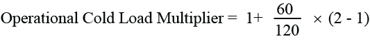
=1.5.
Therefore after the supply had been off for 60 minutes, a multiplier of 1.5 would be applied to the Fault Detect current settings.
So the Operational Cold Load Multiplier would increase linearly from x1 to x2 over a 120 minute period while the supply was off.
When the supply is restored, the Operational Cold Load Multiplier would start at x2 and decrease linearly to x1 over the next 120 minutes if the supply stays on.
While the Cold Load timer is running the controller recalculates the Operational Cold Load Multiplier every minute.
CLP Example
The situation described above is depicted graphically in the figure below.
The Fault Detect setting is 100 A.

Figure 206
Cold Load Time/Current diagram
In this example the supply goes off for four hours. Over the first two hours, the Operational Cold Load Multiplier (OCLM) increases from x1 to x2.
The supply stays off for another two hours but the Operational Cold Load Multiplier doesn’t increase any further because it’s reached its maximum setting.
When the supply comes back on, the load current is significantly higher than usual but doesn’t cause a detection pickup because it doesn’t exceed the Setting Current x the Operational Cold Load Multiplier.
Over the next two hours the Operational Cold Load Multiplier ramps down from x2 to x1 and is always above the load current which also tapers off over that time.
CLP Status
The current status of the CLP
is displayed by WSOS on the Control page.
The Status is read-only and can be either Off, On or Idle.
Off – means that the feature is off and will have no effect on the detection settings.
On – means that at least one of the CLP detection elements is on and the displayed Multiplier is being applied to the Fault Detect setting for that element.
Idle – means that the feature is on but not currently affecting the detection settings.
Time – is the Operational Cold Load Time. Note this field is configurable.
Multiplier – is the current Operational Cold Load Multiplier and is read-only.
The CLP Status is also displayed on the operator interface.
CLP cannot be turned On or Off via the Status display. That can only be done by selecting/deselecting one of the detection elements in the CLP detection settings.
Cold Load Status on Power Up
The CLP status can be changed from the status display by changing the time.
Consider a situation where the load has been off and the controller powered down for some hours due to module replacement/maintenance etc.
The controller was powered down during the outage so when it is powered up again it assumes the load to be diverse that is the Operational Cold Load Time is zero and the CLP status will be Idle.
Because the CLP status time is an operator setting it can be manually adjusted to reflect the duration of the outage and thus allow for the load that might occur when the device goes back into service.
Example
If the CLP settings are:
Cold Load Time 180 minutes
Cold Load Multiplier x3
And it is expected that the Setting Currents need to be doubled for the anticipated increase in load.
That can be achieved by setting
the Cold Load Operational Time to 90 minutes as shown below.
Changing the Operational Cold Load Time automatically changes the Operational Cold Load Multiplier according to the active Cold Load settings.
CLP Summary
-
The user-set Cold Load time and Cold Load Multiplier are protection settings, only the Cold Load Status/Time is an operator setting.
-
Only the protection elements that are selected, Phase, Earth, SEF, and NPS, are affected by the Cold Load Multiplier.
-
Definite Time settings are not affected.
-
CLP cannot be used if normal load currents are expected to drop below 2.5 A.
In this situation, Inrush will use the Operational Cold Load Multiplier if it is the higher.
Table 78 CLP Settings/Specifications
|
CLP Settings/Specifications |
|
|---|---|
|
Cold Load Multiplier Range |
1...5 |
|
Cold Load Multiplier Resolution |
0.1 |
|
Cold Load Time Constant Range |
1...480 min |
|
Cold Load Time Constant Resolution |
1 min |
|
Timing Accuracy |
± 1 min |